BMEWS - 510 Full Days - Detection Radar
 In each of the three transmitter buildings
lay the heart of the AN/FPS-50 Detection Radar (which we newly-arrived Tracker
technicians soon irreverently labelled "Directional Radar"):
the transmitters, receivers, and control systems for transmitter
and receiver switching. The transmitters were on the first floor
of the building. The cabinets which housed the transmitters, receivers,
control units, and consoles were painted a light green, similar
to the 1950's Ford color, "Seafoam green". The inside
of the cabinets was an off-white. On a mezzanine which surrounded
the open building center were the administrative and engineering offices, and
receiver and control cabinets. Also on the mezzanine in each building
was a small radar control room, the Detection Radar Automatic
Monitoring (DRAM) room. The DRAM was responsible for the monitoring
of the transmitters and receivers in that building. The lights
in the DRAM rooms were dimmed so that the indicator lights on
the control consoles could be easily seen. Green lights indicated
a "nominal" component; yellow, a marginal component;
and red, a failure. There were two consoles in each room: one
for the DRAM systems, and the other to control the radar systems
themselves. Because the relative humidity was so low, many times
less than 5 percent, static electricity was an annoyance, but
never seemed to affect the electronic systems. A few minutes of
walking around was sufficient to build up a very large static
charge. "Hush Puppies" shoes, with their foam soles
were especially effective. It was fun to walk into the control
room, move around enough to build up a charge, and touch someone's
ear. The resulting spark would sometimes crack like a .22 rifle
and flash in the dim light like a flashbulb! The victim rarely
thought it was so funny, however.
In each of the three transmitter buildings
lay the heart of the AN/FPS-50 Detection Radar (which we newly-arrived Tracker
technicians soon irreverently labelled "Directional Radar"):
the transmitters, receivers, and control systems for transmitter
and receiver switching. The transmitters were on the first floor
of the building. The cabinets which housed the transmitters, receivers,
control units, and consoles were painted a light green, similar
to the 1950's Ford color, "Seafoam green". The inside
of the cabinets was an off-white. On a mezzanine which surrounded
the open building center were the administrative and engineering offices, and
receiver and control cabinets. Also on the mezzanine in each building
was a small radar control room, the Detection Radar Automatic
Monitoring (DRAM) room. The DRAM was responsible for the monitoring
of the transmitters and receivers in that building. The lights
in the DRAM rooms were dimmed so that the indicator lights on
the control consoles could be easily seen. Green lights indicated
a "nominal" component; yellow, a marginal component;
and red, a failure. There were two consoles in each room: one
for the DRAM systems, and the other to control the radar systems
themselves. Because the relative humidity was so low, many times
less than 5 percent, static electricity was an annoyance, but
never seemed to affect the electronic systems. A few minutes of
walking around was sufficient to build up a very large static
charge. "Hush Puppies" shoes, with their foam soles
were especially effective. It was fun to walk into the control
room, move around enough to build up a charge, and touch someone's
ear. The resulting spark would sometimes crack like a .22 rifle
and flash in the dim light like a flashbulb! The victim rarely
thought it was so funny, however.
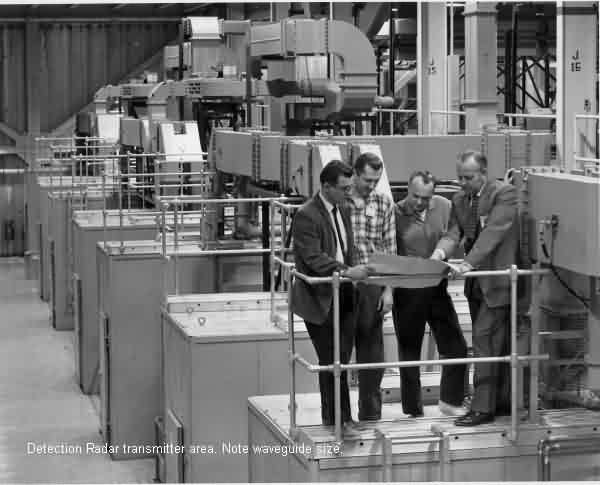
Lined up on the ground floor were the transmitters,
six pairs of 18 inch diameter klystron tubes, manufactured by
Litton Corp., mounted in oil-filled transformers and extending
up through the main floor some 10 feet. Each klystron tube would
provide an average 2.5 megawatts of radar energy on the same frequency
band as 2-meter amateur radio. Each pair of these klystron tubes
was joined by waveguide nearly a yard wide and 18 inches deep,
big enough for a small adult to crawl through. These pairs of
transmitter tubes were routed to waveguide switches which routed
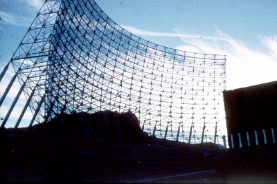
the radar energy out of the building to the scanners.
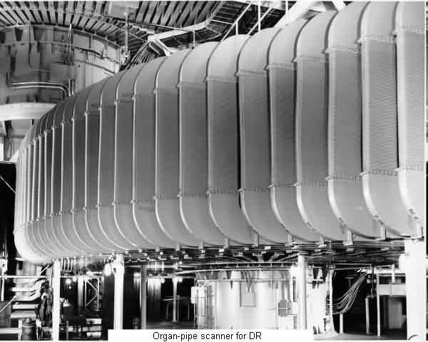
The waveguide
switches allowed any of the transmitter pairs to be switched into
either of the adjacent scanners and allowed transmitters to be
switched in or out as maintenance requirements or equipment failures
dictated. Massive water-cooled dummy loads balanced the transmitter
energy between the switches.
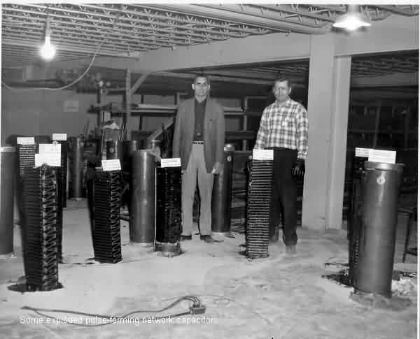
Each pair of klystron tubes was fed from
an electrical charge built up on immense capacitors which lined
the walls of a capacitor vault, an enclosed room about 18 by 30
feet in dimension. The capacitor vaults lay next to the transmitters
against the walls of the main floor, several vaults on each side.
The individual capacitors were cylindrical, about three feet tall
and a foot in diameter. The capacitor vault held dozens of these
capacitors which were connected together to make up the pulse
forming network of the transmitter. Occasionally, a capacitor
would fail, exploding in the vault, blowing the insulating tar-like
substance all over the inside of the vault, sounding just like
dynamite and occasionally causing a small fire.
The first explosion
I heard was frightening, but after hearing several and not having
responsibility for the transmitters, these explosions soon became
just part of the sounds of the site. Never having had to clean
up one of the capacitor vaults, I can nonetheless imagine it to
be a terrible job that is time-consuming, stinking, and perhaps
dangerous.
The middle transmitter building, Building
Two, held the main control room for the radar system and the MIPS
computer room. Special clearance was required to enter both these
rooms. From the central control room, signals travelled to the
other buildings commanding switching transmitters to scanners,
bringing repaired receivers online, and executing other control
tasks. Technicians had to receive permission from the controllers
here in order to take a component offline for service.
The MIPS received signals from the three
transmitter buildings, absorbing information about targets seen
penetrating the detection radar energy beams. The MIPS consisted
of a pair of IBM 7094 mainframe computers. Data from radar targets
was analyzed and calculations made resulting in a prediction of
whether a radar target could be a threat to North America. The
MIPS output was sent to NORAD Headquarters at Cheyenne Mountain,
near Boulder, Colorado. There, on a display panel representing
a map of North America, would be displayed an ellipse which represented
the probable impact area of a missile launched in the Soviet Union.
Happily, with one exception, the only targets displayed on the
display board were those of countless simulations run to test
the effectiveness of the system.
The single exception occurred shortly after
the BMEWS at Thule went into operation. In October, 1960, the
moon rose over the horizon directly in line with one of J Site's
detection radar beams. The engineers who designed the BMEWS system
had apparently not considered that the ultra-high powered radar
beams would reach the moon and in about 2 seconds, return to the
super-sensitive BMEWS receivers. The resulting returns swamped
the MIPS with return information, sending thousands of threat
warnings to Cheyenne Mountain. While the angles, speeds, and doppler
information did not fit the model algorithms of a real threat,
the sheer vastness of the return information overwhelmed the system.
The U.S. did not react to the point that we were brought to the
brink of war, but the doors to Cheyenne Mountain were closed and
locked for several hours while analysts tried to determine the
cause of the fiasco. Once it was understood what caused the problem, a solution was quick to
come. A modification to the radar receivers, called a "Moon
Gater" for its ability to block, or gate, moon returns by
shifting receiver frequency every one-and-a-half seconds, was
designed by RCA engineers and installed on all the BMEWS receivers.
When moonrise was forecast in one of the BMEWS sectors, the Gater
was turned on. Every second and a half, the receiver frequency
shifted, and the returns from the moon were ignored. The frequency
shift caused the receivers to run somewhat detuned, and lights
in the DRAM room routinely turned yellow.
Table of Contents
Next
© Copyright 1996, Gene P. McManus, Baltimore, OH