The AN/FPS-24 Antenna and Radome Issues at Mt Hebo AFS, Oregon
Contributed by Steve Weatherly
The FPS-24 search radar was very large by any measure. Equipment was housed in a 5-story building, 85 feet tall. On top was a huge antenna. Weighing 85.5 tons, the antenna was about 140 feet long and 60 feet high. At Mt Hebo AFS there were four 100 horsepower motors installed to rotate this antenna at 5 rpm under various weather conditions. Winter weather was altogether another antenna issue due to the added weight of ice, greater wind resistance, and the potential for actual damage to the antenna structure. A radome 160 feet in diameter, and about 90 feet tall was to provide the solution. Construction of radome #1 began in Sep 62, but it collapsed during construction in high winds in Oct 62. Radome #2 construction began in Sep 63 and was completed. Lightning and high winds collapsed radome #2 in Jan 64. So operating the FPS-24 without a radome during the winter was tried, but suspended due to ice buildups. By 65 shooting at the FPS-24 antenna with shotguns and spraying it with deicing fluid to dislodge ice buildups had become part of the historical lore of Mt Hebo AFS. It had become an operational imperative that the FPS-24 antenna must have a radome to operate during the winters at Mt Hebo AFS. Operations without a radome had resulted in damage to the FPS-24 antenna that had to be fixed. What follows addresses the aftermath of the ice damage from 61 through the winter of 64/65.
In 1965 the FPS-24 antenna was repaired along with the addition of radome #3. Repairs to the antenna were necessary because of many factors. The first 2 radomes had collapsed around the antenna. Panels that made up these radomes were about 5.5 inches thick, were comprised of an interior resin impregnated cardboard honeycomb, and covered with a thin fiberglass panel. Falling from any height, these radome panels were heavy and large enough to damage the antenna or injure personnel. In addition, since radome #1 was under construction when the radome collapsed, the web of metal pipe scaffolding supporting the incomplete radome was a hazard to the antenna and personnel. However, by the winter of 64/65 it was probably the ice that accumulated on the antenna that was the primary cause for antenna damage. The outer 40 feet on each end of the antenna was visibly bent downwards. These outer antenna wing tips were built up from aluminum tubing vice steel tubing used in the middle sections of the antenna. This tubing was large in diameter (many were at least 10 inches around) and of varying wall thickness. Throughout the antenna there were some compression failures as evidenced by bent or bulging tubing. It was tensile failures that pulled joints apart and visibly tore open tubing that was the most obvious form of FPS-24 antenna structure failure.
When I got to Mt Hebo in Jun 65, the FPS-24 had not been operational for over a year because of the antenna damage described. Repairs included replacing the outer 40 foot FPS-24 antenna wing tips with those from the recently closed FPS-24 at Cottonwood AFS, Idaho. Steel tubing within the rest of the antenna was repaired or replaced. As these repairs were underway, the antenna structure was adjusted to match the dimensions associated with its` shape as recorded during original assembly.
Of interest, only the FPS-24s at Mt Hebo and Cottonwood had radome support structures (RSS) surrounding the 5 story, 85 ft tall FPS-24 building. This radome support structure was helpful during the radome #3 construction and antenna repairs. A storable crane assembly (A frame) was part of the radome support structure and was used to bring materials up from the ground through the maintenance opening in the radome support structure deck. Another crane (Kroll) was provided as part of radome #3 and used for radome construction and some antenna repair. The Kroll crane was mounted on a circular track on top of the radome support structure and FPS-24 building. The Kroll crane and could reach any location atop the FPS-24 building and radome support structure.
This FPS-24 antenna narrative ends with the collapse of radome #3 in 1968. Without a radome the FPS-24 operation at Mt Hebo AFS could not be sustained. The Air Force decided not to provide another radome and the FPS-24 was replaced by the FPS-27 that used a much smaller and more survivable radome.
For those of us who worked in the Radar Operations/FST-2/Comm Center building, the FPS-26A tower, and the FPS-90 tower there was another issue of concern with icing. Pieces of ice would fall off the FPS-24 antenna and Radome Support Structure. Squadron plans called for an evacuation of these buildings when there was icing and winds above 50 mph. In addition, by the spring of 65 the damaged FPS-24 antenna (85.5 tons) was in danger of collapsing. No one wanted to be around for this and the collapses of radome #1 (Oct 62) and radome #2 (Jan 64) had caused considerable damage to buildings and radar facilities below the FPS-24 building. Fortunately there were no personnel injured during these events, but the message was clear, fix or remove the FPS-24 antenna.
Steve Weatherly
Radar Maintenance Officer
Mt Hebo AFS 65-67
Photos associated with AN/FPS-24 antenna issues
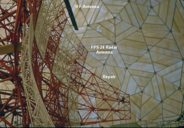
Wingtip repair area - outer 40 feet on either end of antenna.
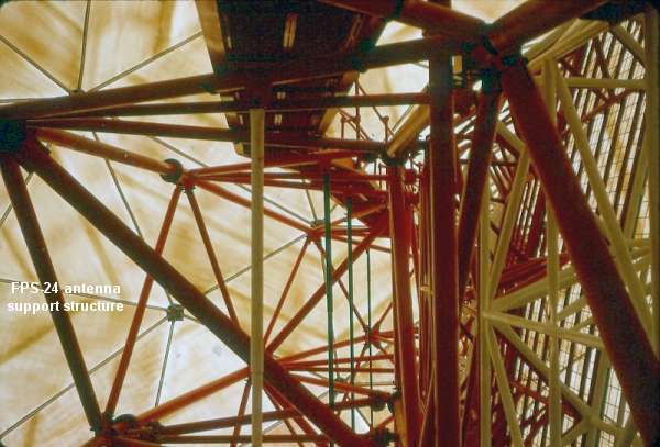
Metal tubes forming antenna support structure.
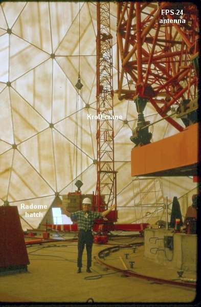
Kroll crane inside radome #3. Base of FPS-24 antenna to the right.
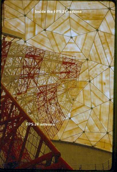
Repaired FSP-24 antenna and new radome #3.
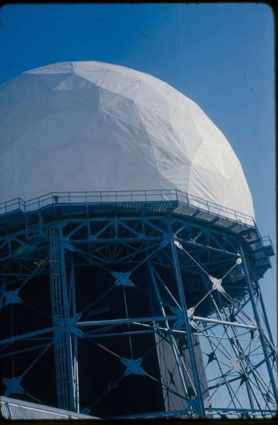
FPS-24 Radome Support Structure (RSS) with new radome #3 completed in 1965. The radome rested on the RSS and not the FPS-24 building. The view from the catwalk of the RSS was breathtaking!
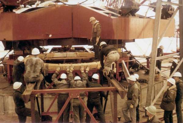
In the photo above, the 12 foot diameter FPS-24 antenna bearing is being replaced in 1967. The 85.5 tone antenna has been jacked up to permit removal of the old bearing and insertion of the new bearing.
One of the two "A" frames for the Mt. Hebo Radome Support Structure (RSS) is seen at the right. These "A" frames were stowed over the hatch in the floor of the RSS. When needed, they were cranked into a vertical position and a horizontal "I" beam with winch was attached between them. The door over the deck hatch could then be removed for access to the ground 85 feet below.