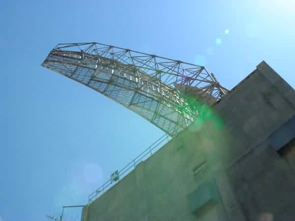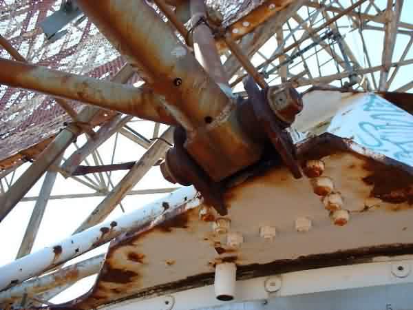
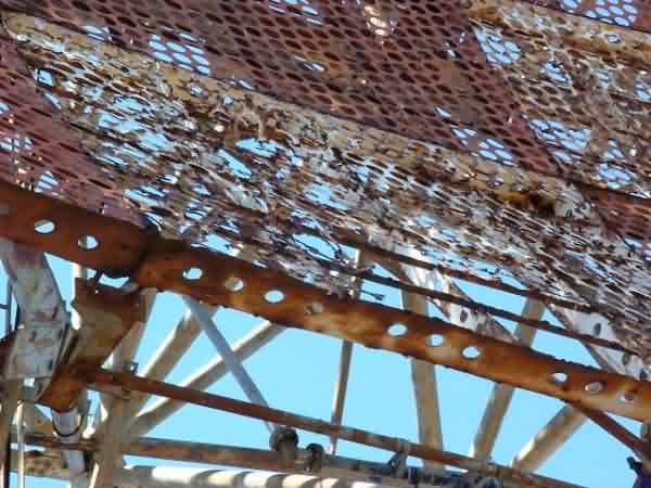
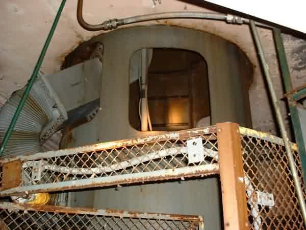
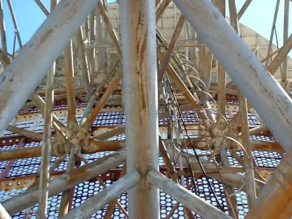
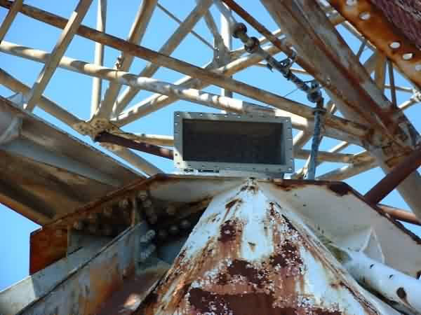
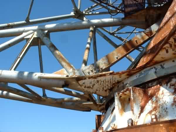
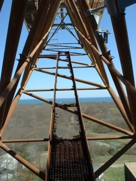
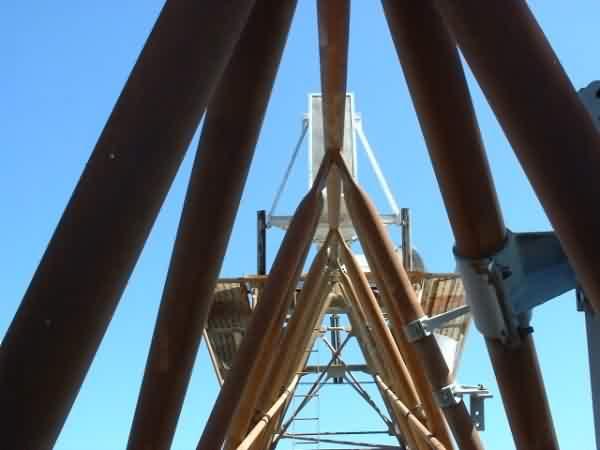
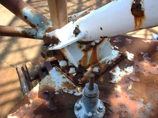
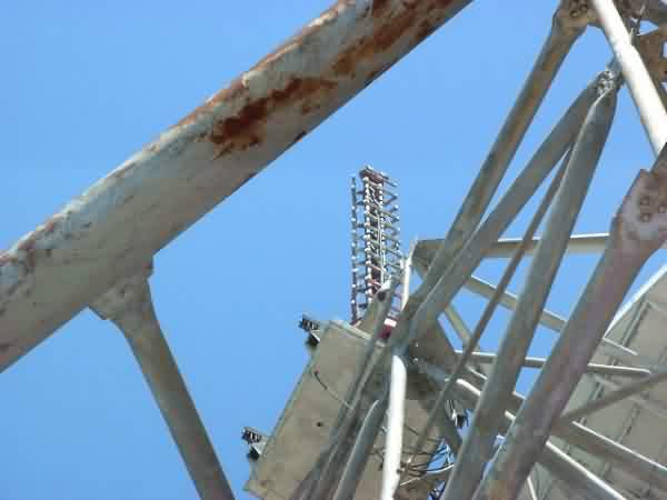
The antenna pedestal structure seemed to be in sound condition despite areas of surface rust. The feedhorn support structure mounts at the pedestal were very rusty, but solid.
Ed. Note: While Walt states some dismay at missing pieces, such as waveguide sections, I think it`s quite heartening that there is so much equipment left. With preservation and restoration, this could at least look like an operational system, with only a very few exceptions.
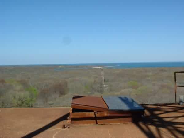
My visit to Camp Hero and the FPS-35 went smoothly thanks to Jim Warren, Tom Dess and his staff, specifically John Rocker who got us started with a brief stop on each floor on the way to the roof where he left us for about 45 minutes. He returned with Richie who stayed with us for the remainder of the visit. Myself and a helper spent about 2 hours assessing the site and I took 80 digital color pictures.
The antenna pedestal structure seemed to be in sound condition despite areas
of surface rust. The feedhorn support structure mounts at the pedestal were
very rusty, but solid.
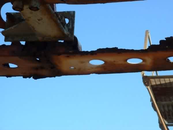
I saw only one small horizontal support tube right at the pedestal that is
part of the rear main support that had severe rust and missing metal, but it
didn`t seem to be a significant part of the overall support structure.
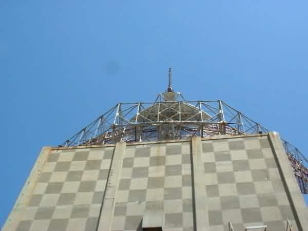
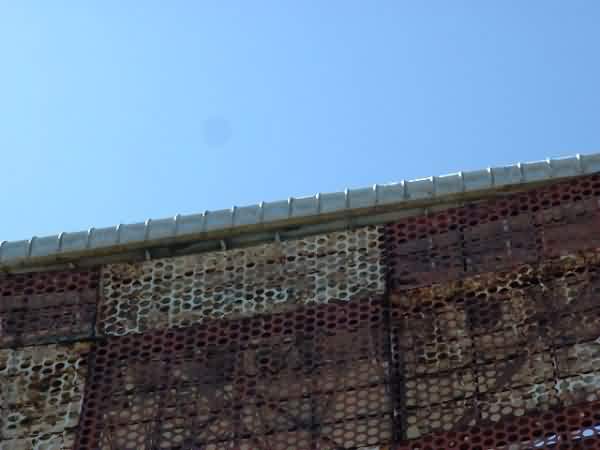
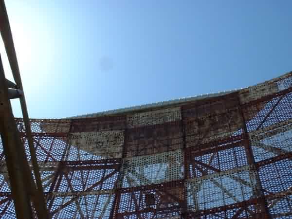
The dish reflector and it`s supports were very rusty with evidence of severe
corrosion and there were areas of missing metal along the lower edges.
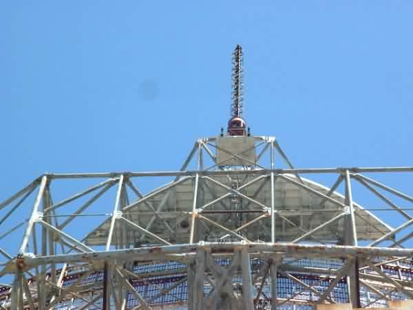
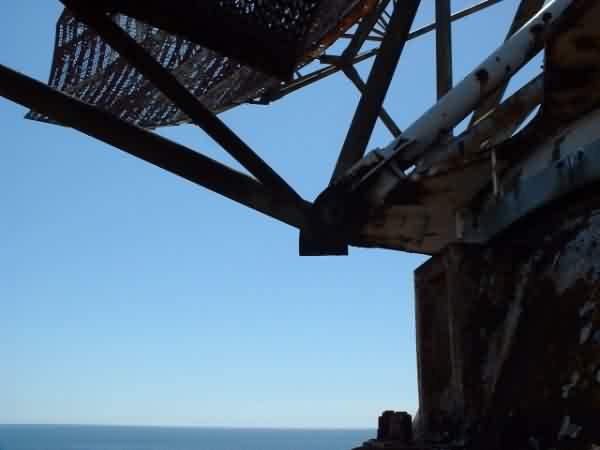
I was not about to climb higher than the top center of the pedestal without safety rigging so I was unable to determine the condition of the top of the dish, or the other two antennas at the top of the main dish.
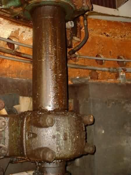
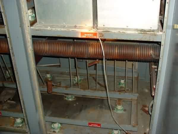
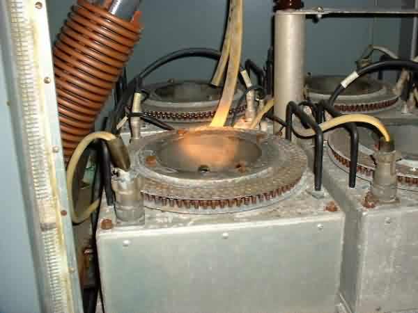
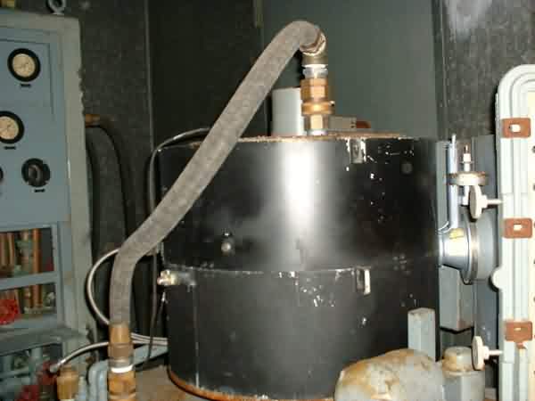
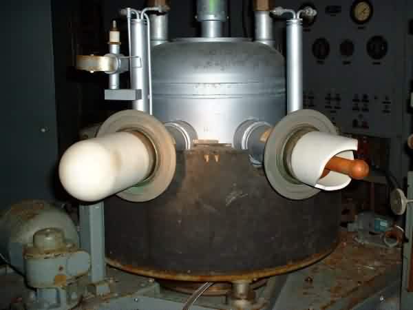
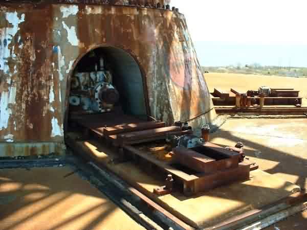
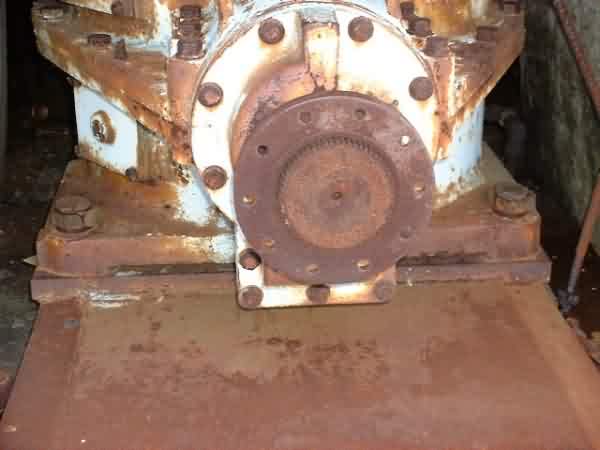
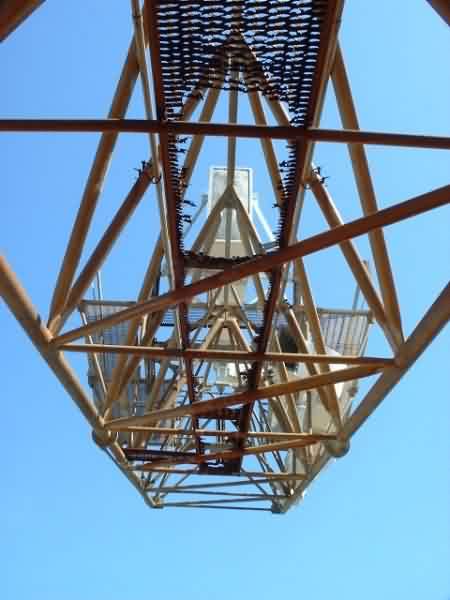
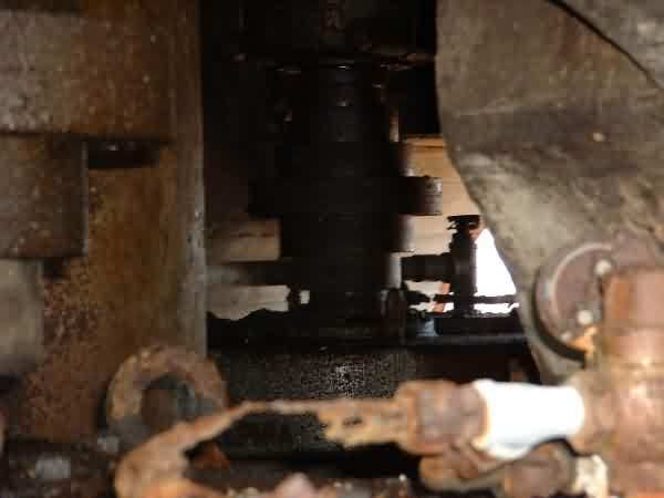
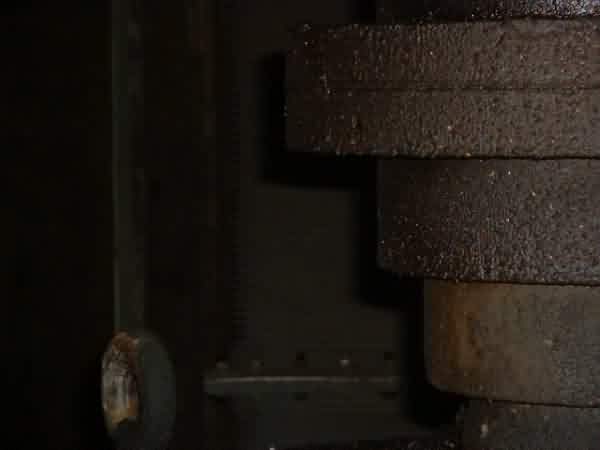
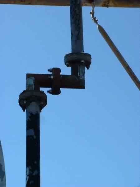
I discovered a possible reason why the dish no longer free-wheels. Two of
the six transmissions do not rotate and their input shafts appear rusted in
place. These are the two closest transmissions to the ocean exposure. I
was able to turn the input shafts of the other 4 transmissions from stop to
stop within the drive gear to bull gear backlash and saw their respective
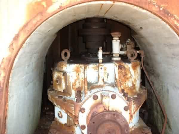
output shafts move. The fact that the dish was free to rotate in the past
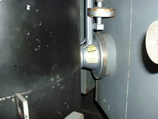
combined with a quick check of Philadelphia Gear`s website leads me to
believe that these are bevel gear transmissions which allow movement when
force is applied at either end--input shaft or output shaft. If these were
worm gear drives, they would work only in one direction and would not allow
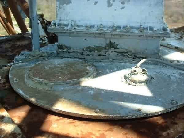
the dish to free-wheel. IF the bull gear and rotary joint is not
mechanically frozen in place due to rust, freeing up the two rusted input
shafts may be all that is needed. Other options include removing the
respective output shafts or drive gear driveshafts.
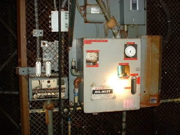
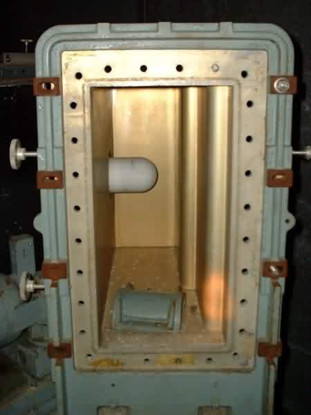
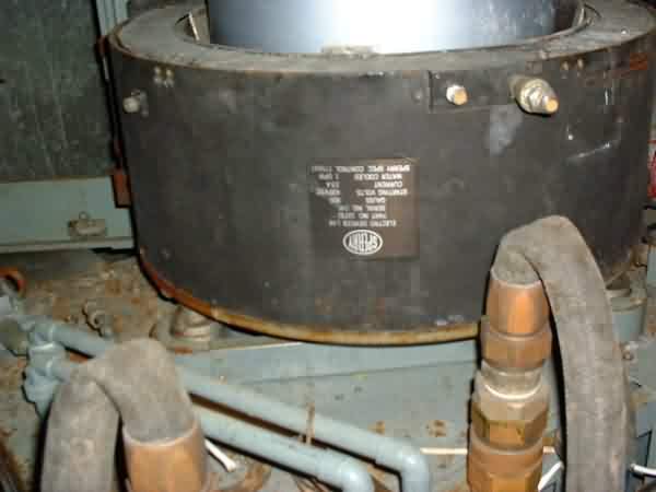
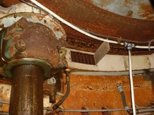
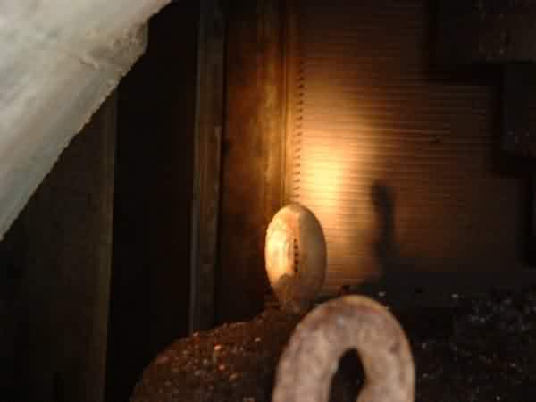
If the bull gear and its bearings are dry or rusted, several options might
be tried. Most of the existing Alemite Oil-Mist system is in place as well
as the associated plumbing to deliver oil to the gear/bearings.
Manually pumping first a penetrating oil and then a more viscous lubricating oil into the existing supply lines might be sufficient for the minimal movement expected for wind direction changes. Once this is done, a few people muscling the input shafts might be able to turn the dish. If not, careful persuasion from a come-along attached between the antenna structure and one of the rigid eyes on the tower might work.
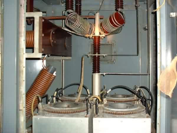
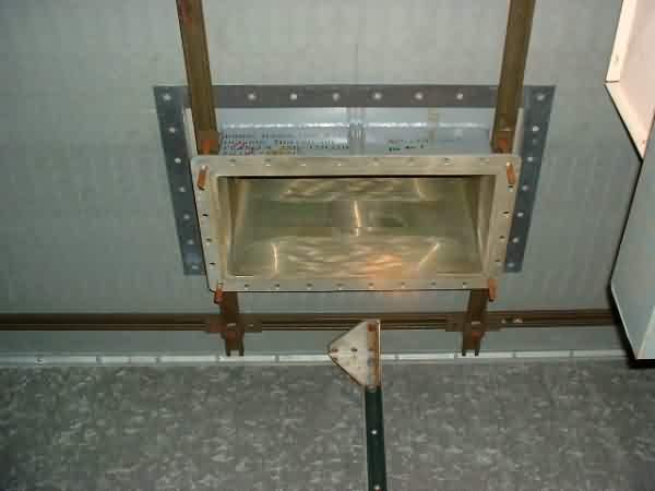
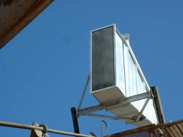
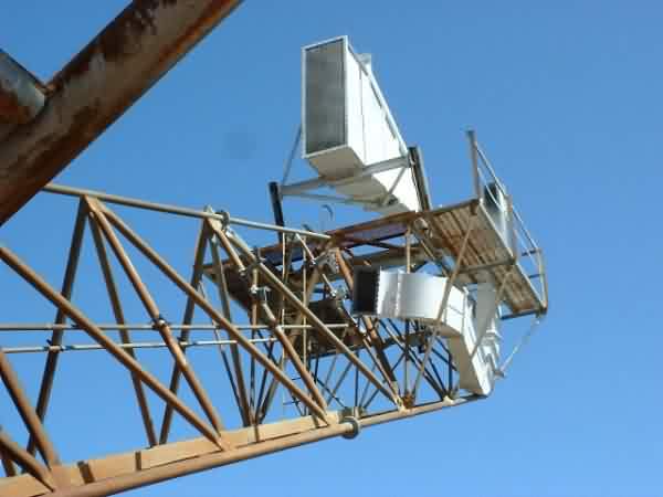
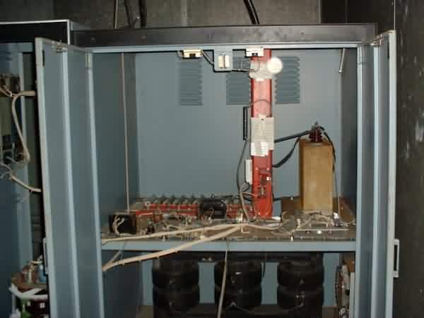
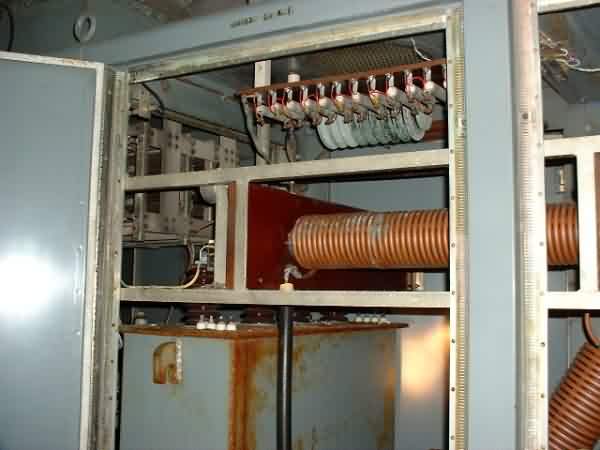
Regarding painting and preserving the antenna--since the structure looks sound, it might be possible to work on it in place with rigging and/or scaffolds. Perhaps a Bridgepainters Local might be able to help? I was surprised at how little of the transmitting equipment was left. I especially noticed the absence of the rigid waveguide sections. Where did it all go? I can`t think of why it would have been valuable to someone else unless it had gold or silver plating inside.


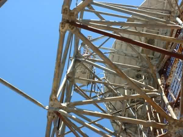
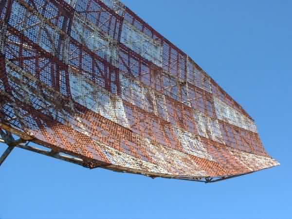
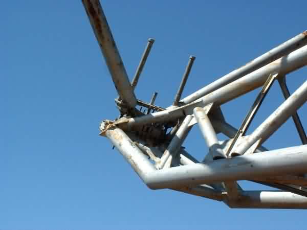
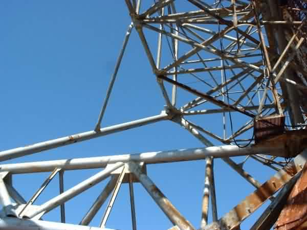

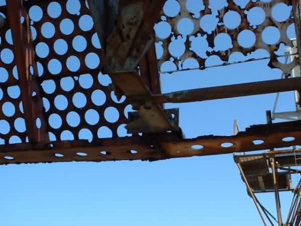
Note: 2 transmissions on ocean side do not rotate (rusted input shafts?) Rear support structure has less rust than other portions of A/P and appears to be structurally sound. The reflector side, however, is severely rusted and has sections of missing metal. There are several missing sections of support structure for the reflector skin.
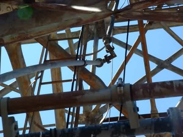
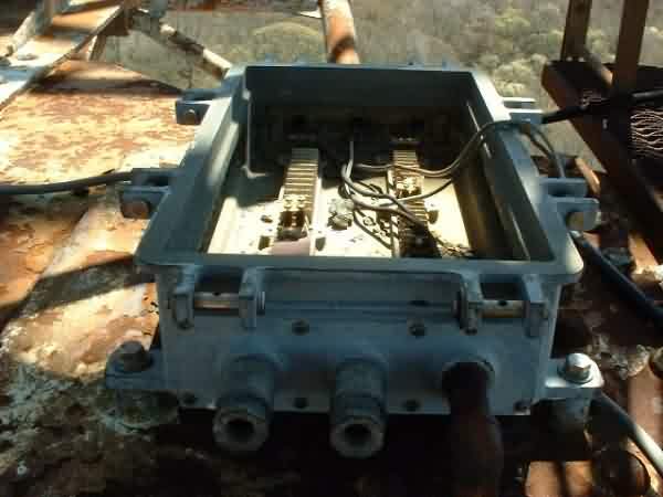
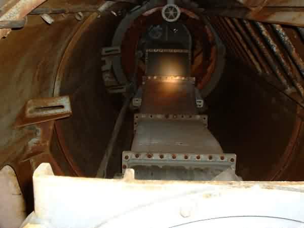
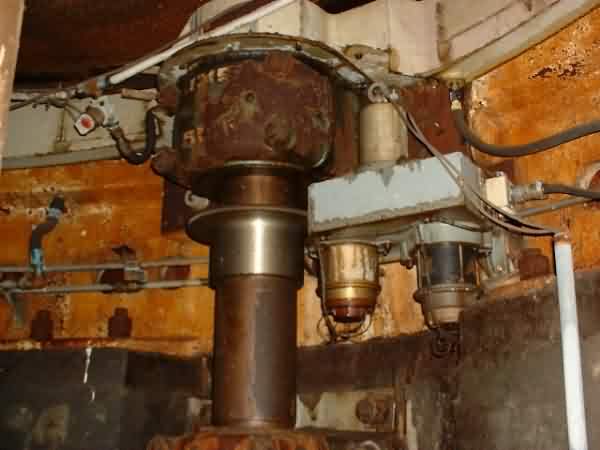
Note: Looks like a pressure fed oiling system. Plumbing around circumference with taps at each point where drive gears mesh with bull gear. Also taps for what looks like oil returns.
<
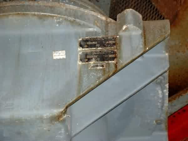
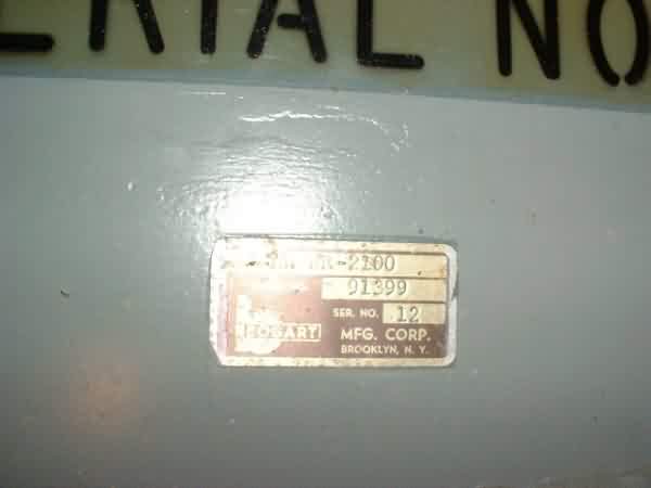

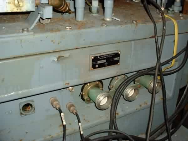
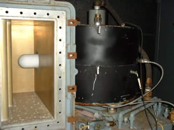
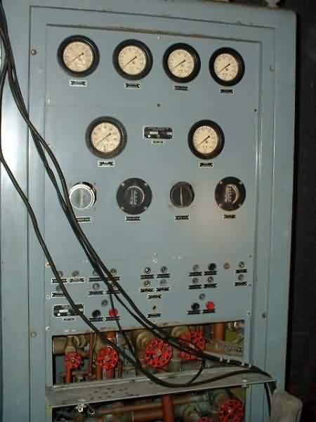
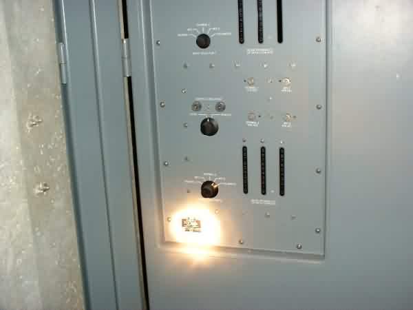
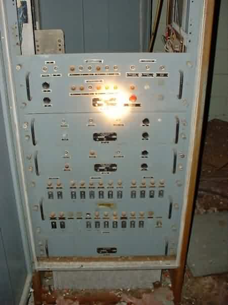
Nameplate on Amplifier/Modulator equipment cabinet:
Equip. Group: OA-4678/FPS-35
S/N: 22
P/N: 1035219
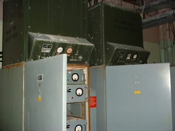
P/N: 1018026
S/N: 3